
Valve Guide Cutters: A Comprehensive Guide
Valve guide cutters are specialized tools for precise guide creation, utilizing annular, trepanning, or hollow mill methods;
rigid machines are crucial for optimal results․
What is a Valve Guide Cutter?
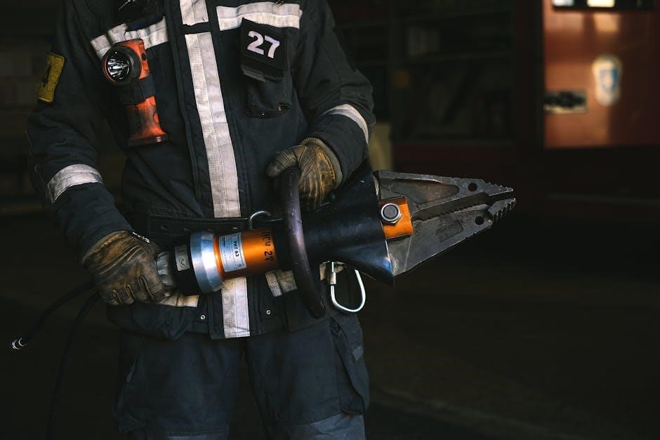
A valve guide cutter is a precision machining tool specifically designed to create or re-condition the internal diameter of valve guides within cylinder heads․ These guides ensure accurate valve alignment and smooth operation․ Several types exist, including Rotabroach annular cutters, which are cost-effective, and trepanning tools used with boring heads – requiring a notably rigid machine due to their wide cutting action․
Furthermore, hollow mill cutters offer another option, and specialized carbide-tipped valve guide cutting tools provide durability and precision when cutting guides to a specific outside diameter, like ․500 inches․ The selection depends on the workshop’s needs and the machine’s capabilities, with considerations for arbor/pilot sizes, such as those for 11/32 valves․
The Purpose of Valve Guides
Valve guides are critical components within an engine’s cylinder head, serving as a precise bearing surface for the valve stems․ Their primary function is to maintain correct valve alignment during operation, preventing side loading and ensuring a proper valve seal against the valve seat․ This precise alignment is essential for efficient combustion and optimal engine performance․
Without properly functioning valve guides, valves can wander, leading to burnt valves, reduced compression, and ultimately, engine failure․ They also contribute to consistent valve control, especially at high engine speeds․ Considering valve guides as separate, press-fit pieces into the head is a viable installation method, highlighting their importance as individual, replaceable components․
Why Use a Valve Guide Cutter?
Valve guide cutters become necessary during engine rebuilds or cylinder head repairs when existing guides are worn, damaged, or need replacement․ Precise guide dimensions are paramount for optimal valve train function, and a cutter ensures accurate sizing for a proper fit․ Utilizing tools like Rotabroach annular cutters or trepanning tools allows for the creation of new guides, or the resizing of existing bores․
A rigid machine is essential when employing these cutters, given the wide cuts involved․ Furthermore, using a cutter allows for the installation of press-fit valve guides, offering a robust and reliable solution․ Choosing the correct cutter, considering material compatibility (steel or carbide), is vital for a successful outcome․
Types of Valve Guide Cutters
Various cutters exist, including Rotabroach annular, trepanning tools with boring heads, hollow mills, and carbide-tipped options, each suited for different applications and budgets․
Rotabroach Annular Cutters
Rotabroach annular cutters represent a cost-effective solution for valve guide creation, frequently mentioned as a more affordable alternative to other methods․ These cutters operate by removing material in a circular fashion, creating a precise bore for the valve guide․ Their design allows for relatively quick material removal, making them a popular choice for workshops and machinists․
However, utilizing Rotabroach cutters effectively necessitates a robust and rigid machine tool․ The cutting process generates significant forces, and a lack of machine rigidity can lead to inaccuracies and potentially damage the cutter or the workpiece․ Proper setup and secure clamping are paramount for achieving optimal results․ Considerations regarding shipping costs and customs duties may arise when sourcing these cutters internationally․
Trepanning Tools with Boring Heads
Trepanning tools, when combined with a boring head, offer another avenue for valve guide installation․ This method involves utilizing a specialized cutting tool to remove a large diameter of material, effectively creating the bore for the valve guide․ The process resembles a wide cut, demanding a particularly rigid machine to counteract the substantial forces generated during operation․
The advantage of trepanning lies in its ability to efficiently remove material, but it requires careful control and a stable machining setup․ Machine rigidity is absolutely critical to prevent chatter, ensure accuracy, and avoid tool breakage․ This technique is often considered when dealing with larger valve guide bores or when a high degree of precision is required․
Hollow Mill Cutters
Hollow mill cutters represent a viable option for valve guide creation, offering a distinct approach to material removal․ These cutters feature a hollow cylindrical design, allowing them to directly mill out the bore required for the valve guide․ A potential benefit is the availability of these tools; one source indicated a possible 1/2-inch hollow mill cutter might be loaned, contingent on shipping and customs considerations․
While effective, hollow mill cutters necessitate a robust machine setup to manage the cutting forces․ The process demands precision and control to achieve the desired bore diameter and surface finish․ Careful consideration of cutter geometry and machining parameters is essential for optimal results․ This method provides a direct and relatively straightforward path to valve guide installation․
Carbide Tipped Valve Guide Cutting Tools
Carbide tipped valve guide cutting tools offer enhanced durability and performance compared to standard steel cutters․ The carbide tip provides superior resistance to wear, extending tool life and maintaining cutting accuracy, especially when working with hardened materials․ These tools are specifically designed to cut guides with a ․500-inch outer diameter, catering to common valve guide sizes․
Selecting the correct arbor and pilot size is crucial for precise alignment and cutting․ For example, a 11/32-inch arbor/pilot is available for valves of that size; Carbide tipped cutters represent a significant investment, but their longevity and ability to deliver clean, accurate cuts make them a valuable asset in any machine shop focused on valve train work․
Key Specifications & Considerations
Essential factors include cutting diameter (․500 in․ O․D․), arbor/pilot sizes (11/32 valves), and material compatibility – steel or carbide – for optimal performance․
Cutting Diameter (e․g․, ․500 in․ O․D․)
The cutting diameter is a primary specification when selecting a valve guide cutter, directly determining the outer diameter (O․D․) of the created valve guide․ Commonly, cutters are available to achieve specific dimensions, such as ․500 inches O․D․, catering to a wide range of engine applications and valve guide requirements․
Choosing the correct diameter is critical for ensuring proper valve alignment and preventing binding․ Incorrect sizing can lead to premature wear, reduced engine performance, and potential valve failure․ Precision is paramount; therefore, verifying the required valve guide O․D․ for the specific engine being serviced before cutter selection is essential․
Different engines necessitate different guide diameters, so a versatile set of cutters or a cutter with adjustable diameters can be a valuable investment for any machine shop․
Arbor/Pilot Sizes (e․g․, 11/32 Valves)
Arbor and pilot sizes are crucial for accurate valve guide cutting, ensuring the cutter is precisely centered on the valve guide bore․ Pilots, often specified by valve stem diameter (e․g․, 11/32 valves), guide the cutter and maintain concentricity during the cutting process․
Selecting the correct pilot is vital; a mismatch can result in off-center guides, leading to valve misalignment and performance issues․ Arbors provide the mounting interface for the cutter and pilot, and must be compatible with the machine’s spindle․
Compatibility between the arbor, pilot, and cutter is essential for a secure and accurate setup․ A range of pilot sizes allows for versatility across different engine types and valve stem diameters, making a comprehensive set a worthwhile investment․
Material Compatibility (Steel, Carbide)
Valve guide cutters are available in steel and carbide tipped varieties, each suited for different applications and materials․ Steel cutters are generally more economical, ideal for softer guide materials and lower production volumes; However, they wear more quickly․
Carbide tipped cutters offer significantly increased wear resistance, making them perfect for high-volume production and harder guide materials like powdered metal alloys․ The carbide tip maintains a sharp cutting edge for longer, improving accuracy and surface finish․
Choosing the right material depends on the guide material, production quantity, and budget․ Carbide is a superior choice for durability, while steel provides a cost-effective solution for less demanding tasks․
The Valve Guide Cutting Process
Rigid machines are essential for valve guide cutting, requiring precise pilot hole preparation, controlled cutting speeds, and thorough dimensional verification for accuracy․
Machine Rigidity Requirements
Achieving accurate valve guide installations demands exceptional machine rigidity․ The cutting process, particularly when employing trepanning tools or wider hollow mills, generates substantial forces․ A lack of rigidity manifests as chatter, leading to inaccurate guide dimensions and potentially damaging the cylinder head․
The machine’s structure – including the spindle, table, and supporting components – must minimize deflection under load․ Consider the material of the machine; cast iron generally offers superior damping and rigidity compared to lighter alloys․
Properly tightened and maintained components are also vital․ Regularly inspect and address any play in the machine’s ways or spindle bearings․ Furthermore, secure workholding is paramount; a robust vise or fixture prevents movement during the cutting operation, contributing to overall precision and a quality finish․
Pilot Hole Preparation
Precise pilot hole preparation is fundamental for accurate valve guide cutting․ The pilot hole serves as the initial guide for the cutter, establishing the concentricity and alignment of the new guide․ Typically, a standard drill bit, sized appropriately for the chosen arbor and pilot combination, is used to create this hole․
Ensure the pilot hole is perpendicular to the cylinder head surface; any angularity will translate into a misaligned valve guide․ Deburring the pilot hole after drilling is crucial to prevent the cutter from binding or wandering during the cutting process․
Carefully select the drill bit material to match the cylinder head’s composition, avoiding chipping or damage․ A clean, accurately sized pilot hole significantly enhances the overall quality and precision of the valve guide installation․
Cutting Speed and Feed Rate
Determining the correct cutting speed and feed rate is vital for efficient and accurate valve guide cutting․ These parameters depend heavily on the cutter type – annular, trepanning, or hollow mill – and the material being cut (steel or cast iron)․ Generally, slower speeds and consistent feed rates yield superior finishes and minimize tool wear․
A rigid machine is essential, as higher feed rates demand substantial stability․ Excessive speed can cause chatter, leading to inaccurate dimensions and potential damage to both the cutter and the cylinder head․
Experimentation and careful observation are key; start conservatively and gradually increase the feed rate until optimal performance is achieved, always prioritizing precision over speed․
Measuring and Verifying Guide Dimensions
Precise measurement is paramount after utilizing a valve guide cutter․ Employing high-quality measuring instruments – micrometers and calipers are essential – ensures the newly cut guide meets stringent dimensional requirements․ Verify both the inner and outer diameters, comparing them against the manufacturer’s specifications for the specific valve and cylinder head․
Consistent checks throughout the cutting process are advisable, not solely at the completion․
Any deviations from the specified dimensions necessitate corrective action, potentially involving slight adjustments to the cutting parameters or, in severe cases, re-cutting the guide․ Accuracy directly impacts valve train performance and engine longevity․
Alternative Methods for Valve Guide Installation
Press-fitting offers an alternative to cutting, where valve guides are installed as separate components, securely pressed into the cylinder head for a robust fit․
Press-Fit Valve Guides
Employing press-fit valve guides represents a viable alternative to the machining process utilizing valve guide cutters․ This method involves utilizing separate, precisely sized valve guide components that are then mechanically installed into the cylinder head․ The interference fit created during pressing ensures a secure and durable bond, eliminating the need for cutting and reaming operations․
However, successful implementation of press-fitting demands meticulous attention to detail․ Proper preparation of both the valve guide bore in the head and the outer diameter of the guide itself is paramount․ Controlled heating of the head or cooling of the guides can facilitate installation, minimizing stress and ensuring accurate alignment․ This technique is particularly advantageous when dealing with materials or head designs where machining presents challenges, offering a reliable and efficient solution for valve guide installation․
Tools and Accessories
Essential accessories include arbors, pilots sized for valves (like 11/32), coolant for lubrication, and precise measuring instruments—micrometers and calipers—for verification․
Arbors and Pilots

Arbors serve as the foundational mounting point for valve guide cutters, securely holding them within the machining setup․ They come in various sizes to accommodate different cutter diameters and machine spindle configurations․ Pilots, crucial for accurate centering, are inserted into the valve guide bore before cutting․
Selecting the correct pilot size is paramount; a common size is specified for 11/32 valves, ensuring a precise fit․ The arbor and pilot work in tandem to guide the cutter, maintaining concentricity and preventing damage to the cylinder head․ High-quality arbors are typically made from hardened steel for durability and minimal runout․ Proper arbor and pilot selection guarantees a clean, accurately sized valve guide, essential for optimal engine performance and longevity․ Mismatched components can lead to inaccuracies and potential engine failure․
Coolant and Lubrication
Coolant and lubrication are indispensable during valve guide cutting, mitigating heat buildup and reducing friction between the cutter and the workpiece․ Excessive heat can distort the cylinder head and dull the cutting tool prematurely, compromising accuracy․ Appropriate coolants, often oil-based or synthetic formulations, flush away chips and provide a lubricating film․
Consistent coolant application is vital, especially when utilizing carbide-tipped cutters or working with harder materials․ Proper lubrication extends tool life, improves surface finish, and prevents galling․ The choice of coolant should be compatible with both the cutter material and the cylinder head alloy․ Insufficient lubrication can lead to rapid tool wear and a rough, inaccurate valve guide bore, ultimately affecting valve train performance and engine reliability․
Measuring Instruments (Micrometers, Calipers)
Precise measurement is paramount throughout the valve guide cutting and installation process․ Micrometers and calipers are essential tools for verifying critical dimensions, ensuring proper fit and function․ Before cutting, accurately measure the existing guide bore and the new guide’s outer diameter․
Post-cutting, micrometers confirm the final guide inner diameter and wall thickness, adhering to manufacturer specifications․ Calipers assess the guide’s height and alignment within the cylinder head․ Consistent checks throughout the process prevent errors and guarantee a precise, interference-fit installation; Utilizing high-quality, calibrated instruments is crucial for achieving optimal valve train geometry and maximizing engine performance․ Accuracy directly impacts valve sealing and longevity․
Safety Precautions
Always wear eye protection during valve guide cutting․ Ensure proper machine guarding is in place, and handle materials carefully to prevent injuries․
Eye Protection
When operating valve guide cutters, prioritizing eye protection is absolutely paramount․ The cutting process generates high-velocity metal chips and debris, posing a significant risk of serious eye injury․ Standard safety glasses simply aren’t sufficient; full-face shields are strongly recommended to provide comprehensive coverage․
These shields protect not only your eyes but also your face from flying particles․ Ensure the face shield is ANSI Z87․1 rated, indicating it has passed rigorous impact resistance testing․ Regularly inspect your face shield for scratches or damage, replacing it immediately if any imperfections are found․ Never attempt to operate a valve guide cutter without adequate eye and face protection – it’s a non-negotiable safety measure․
Proper Machine Guarding
Utilizing proper machine guarding is essential when employing valve guide cutters, given the high speeds and forces involved․ Ensure all machine guards are securely in place and functioning correctly before commencing any cutting operation․ These guards are designed to contain flying chips and prevent accidental contact with rotating parts․
Specifically, check spindle guards, chuck guards, and any shields protecting the cutting tool’s path․ Never override or disable safety interlocks on the machine․ Regularly inspect guards for damage or wear, promptly repairing or replacing any compromised components․ A rigid machine is needed, so ensure it is stable․ Maintaining a safe working environment through diligent machine guarding significantly reduces the risk of injury during valve guide cutting procedures․
Material Handling
Safe material handling is paramount when working with valve guides and the associated cutting tools․ Always use appropriate lifting techniques and equipment to avoid strain or injury when moving heavier components like cylinder heads․ Be mindful of sharp edges on both the valve guides themselves and any metal chips generated during the cutting process․
Dispose of metal chips responsibly, utilizing designated containers and following proper waste management procedures․ When handling cutters, especially carbide-tipped varieties, wear gloves to prevent cuts and maintain a firm grip․ Consider shipping costs and customs if borrowing tools․ Securely store all tools and materials when not in use, preventing accidental damage or unauthorized access․