Wanderer Solar Charge Controller Manual: A Comprehensive Guide
This manual details setup, operation, and troubleshooting for Wanderer controllers, leveraging LLMs and RAG for datasheet specification extraction, as of 04/01/2026.
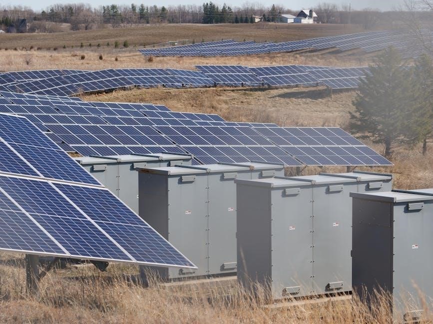
Wanderer Solar Charge Controllers are designed to optimize the energy harvest from your solar panels, ensuring efficient and reliable charging of your battery bank. These controllers act as the crucial link between your solar array and batteries, preventing overcharging and extending battery life.
Recent advancements, utilizing Large Language Models (LLMs) and Retrieval-Augmented Generation (RAG), are streamlining the process of extracting key specifications directly from datasheets. This allows for a more informed user experience and simplifies the selection of the appropriate controller for your specific needs.
This guide provides a comprehensive overview, covering everything from basic operation to advanced customization, all based on current information as of April 1st, 2026. Understanding your Wanderer controller is key to maximizing your solar investment.
Understanding Charge Controller Types
Wanderer offers both PWM (Pulse Width Modulation) and MPPT (Maximum Power Point Tracking) charge controllers, each suited to different system requirements. PWM controllers are a more traditional, cost-effective solution, ideal for smaller systems where panel voltage closely matches battery voltage. They function by rapidly switching the connection between the solar panel and battery.
MPPT controllers, however, represent a significant technological leap. Utilizing advanced algorithms, they maximize energy harvest by continuously tracking the optimal voltage and current from the solar panels, even when panel voltage exceeds battery voltage. This is particularly beneficial in larger systems or those with varying weather conditions.
The choice between PWM and MPPT depends on factors like system size, budget, and desired efficiency, with LLM-powered tools aiding in optimal selection based on extracted datasheet specifications.

2.1 PWM (Pulse Width Modulation) Controllers
Wanderer’s PWM charge controllers offer a reliable and economical solution for simpler solar setups. They operate by connecting and disconnecting the solar panel to the battery, modulating the width of the pulse to control the charging rate. This method is effective when the solar panel voltage is closely aligned with the battery voltage, minimizing energy loss.
PWM controllers are generally less expensive and easier to implement than MPPT controllers, making them a popular choice for smaller off-grid systems or supplemental charging applications. They are robust and require minimal maintenance, providing years of dependable service.
However, PWM controllers don’t maximize energy harvest in all conditions, particularly when panel voltage significantly exceeds battery voltage. Datasheet analysis via RAG helps determine suitability.
2.2 MPPT (Maximum Power Point Tracking) Controllers
Wanderer’s MPPT (Maximum Power Point Tracking) charge controllers represent a significant advancement in solar charging technology. These controllers actively seek the optimal voltage and current combination from the solar panel to maximize power transfer to the battery, regardless of voltage differences.
Utilizing sophisticated algorithms, MPPT controllers continuously adjust the operating point to extract the most energy possible, especially in challenging conditions like partial shading or varying temperatures. This results in significantly higher energy yields compared to PWM controllers, particularly with higher voltage panels.
While more complex and typically more expensive, MPPT controllers are ideal for larger systems and situations where maximizing energy harvest is crucial. RAG-powered datasheet extraction aids in selecting the optimal MPPT model.
Key Features of Wanderer Charge Controllers
Wanderer solar charge controllers are engineered for reliability and performance, offering a suite of features designed to optimize your solar energy system. A core strength lies in their broad battery compatibility, supporting lead-acid, AGM, gel, and various lithium-ion chemistries – crucial for diverse applications.
Intuitive display interfaces provide real-time system monitoring, including voltage, current, power, and state of charge. Advanced models feature customizable charge profiles, allowing users to tailor charging parameters to specific battery requirements.
Leveraging LLM-powered data analysis, Wanderer controllers ensure optimal performance and longevity. Furthermore, robust protection mechanisms safeguard against overcharge, over-discharge, and reverse polarity.
3.1 Battery Compatibility (Lead-Acid, Lithium, etc.)
Wanderer charge controllers demonstrate exceptional versatility through extensive battery compatibility. They seamlessly integrate with traditional lead-acid batteries – flooded, AGM, and gel – offering optimized charging algorithms for each type. Crucially, they also fully support a wide spectrum of lithium-ion chemistries, including LiFePO4, NMC, and others, ensuring safe and efficient charging.
The controllers’ intelligent charging profiles automatically adjust voltage and current based on the selected battery type, maximizing battery lifespan and performance. Users can often customize these profiles further, tailoring them to specific battery specifications. This adaptability, driven by LLM data analysis, makes Wanderer controllers ideal for diverse solar setups.
3.2 Display and Interface Overview

Wanderer charge controllers feature a clear, backlit LCD display providing real-time system information. Key metrics such as battery voltage, charging current, load current, and total energy generated are readily visible. The intuitive interface utilizes a combination of buttons and, in some models, a streamlined menu navigation system.
This interface allows for easy configuration of battery type, charging profiles, and load control settings. Data logging capabilities, accessible through the display, enable performance monitoring and troubleshooting. The RAG-enhanced manual provides detailed explanations of each display element and menu option, ensuring users can effectively monitor and manage their solar power system.

Safety Precautions & Warnings
Prior to installation and operation, carefully review all safety precautions. Incorrect wiring or handling can result in electric shock, fire hazard, or damage to equipment. Always disconnect the battery before making any connections or adjustments to the charge controller.
Ensure proper grounding to minimize the risk of electrical shock and protect against lightning strikes; Do not expose the controller to excessive moisture or extreme temperatures. Use appropriately sized wiring and fuses to prevent overheating and potential fire hazards. Consult a qualified electrician if you are unsure about any aspect of the installation or operation. This manual, leveraging RAG technology, provides critical safety information.
Installation Guide
Proper installation is crucial for optimal performance and longevity of your Wanderer charge controller. Begin by selecting a suitable location – cool, dry, and well-ventilated – away from direct sunlight and moisture. Securely mount the controller using appropriate hardware, ensuring adequate airflow around the unit.
Follow the wiring diagrams meticulously, connecting solar panels, battery bank, and load in the correct sequence. Double-check all connections for tightness and polarity before applying power. Utilize appropriately sized wiring to minimize voltage drop and prevent overheating. This guide, informed by LLM-extracted data, simplifies the process. Refer to subsequent sections for detailed wiring schematics and setup instructions.
5.1 Mounting the Charge Controller
Secure mounting is essential for reliable operation and preventing damage to your Wanderer charge controller. Choose a location that provides adequate ventilation to dissipate heat, avoiding direct sunlight or areas prone to moisture. The controller should be mounted vertically on a solid, non-combustible surface.
Utilize the mounting holes provided on the unit’s chassis. Employ screws or bolts of appropriate size and length, ensuring they are securely fastened but not over-tightened. Maintain a minimum clearance of 10cm around the controller for airflow. Proper mounting, guided by LLM-processed data, contributes to system longevity. Avoid mounting near flammable materials or sources of extreme temperature fluctuations.
5.2 Wiring Diagram – Solar Panels to Controller
Connecting solar panels to the Wanderer controller requires careful attention to polarity and wire gauge. Always disconnect the battery before commencing any wiring. Use appropriately sized, UV-resistant wiring suitable for outdoor use. Connect the positive (+) terminal of each solar panel to the positive input terminal on the controller, and the negative (-) to the negative input terminal.
For parallel connections, ensure all panels have similar voltage and current ratings. Series connections increase voltage; verify the controller’s maximum input voltage is not exceeded. LLM-extracted specifications detail acceptable wiring configurations. Securely tighten all connections to prevent arcing or voltage drop. Double-check polarity before reconnecting the battery.
5.3 Wiring Diagram – Controller to Battery Bank
Connecting the Wanderer controller to the battery bank is a critical step; incorrect wiring can cause damage. Always use a fuse or circuit breaker as close as possible to the battery’s positive terminal for overcurrent protection. Connect the positive (+) terminal of the controller to the positive (+) terminal of the battery bank, and negative (-) to negative (-).
Ensure the wire gauge is sufficient to handle the maximum charging current. Refer to the controller’s specifications (extracted via RAG) for recommended wire sizes. Proper grounding is essential for safety. Verify battery voltage matches the controller’s settings before connecting. Double-check all connections before restoring power.
5.4 Wiring Diagram – Controller to Load
Connecting a DC load to your Wanderer charge controller allows for automated power distribution. Utilize the designated load terminals on the controller – positive (+) and negative (-). Always adhere to the controller’s maximum load current rating, found within the RAG-extracted specifications. A fuse or circuit breaker should be installed inline with the positive load wire, close to the controller.
Ensure the load’s voltage is compatible with the battery bank voltage. Incorrect voltage can damage the load. Consider the load’s power consumption when sizing the battery bank. Proper wiring gauge is crucial to minimize voltage drop. Disconnect the load before making any wiring changes to the system.
Setting Up Your Wanderer Charge Controller

Initial setup is crucial for optimal performance. Begin by verifying the battery bank voltage matches the controller’s input voltage range, utilizing data extracted via RAG from the datasheet. Next, select the appropriate battery type (Lead-Acid, Lithium, etc.) within the controller’s settings. This ensures correct charging profiles are applied.
Customize charge parameters if needed, referencing the specifications for your specific battery chemistry. Pay close attention to absorption and float voltages. Incorrect settings can reduce battery lifespan or cause damage. The controller’s interface allows for fine-tuning these parameters. Document all settings for future reference.
6.1 Battery Type Selection

Accurate battery type selection is paramount for safe and efficient charging. Wanderer controllers support various chemistries, including flooded lead-acid, AGM, gel, and lithium-ion (LiFePO4). Access the settings menu via the controller’s interface and navigate to the ‘Battery Type’ option. Carefully choose the setting that corresponds to your battery bank.
Incorrect selection can lead to undercharging or overcharging, significantly reducing battery lifespan and potentially causing damage. Consult your battery manufacturer’s specifications to confirm the correct setting. The controller utilizes different charging algorithms based on the selected type, optimizing performance. Double-check your selection before proceeding.
6.2 Charge Profiles & Customization
Wanderer charge controllers offer pre-programmed charge profiles tailored to common battery types, ensuring optimal charging performance. However, advanced users can customize these profiles to fine-tune the charging process based on specific battery characteristics or environmental conditions. Access the ‘Charge Profile’ settings through the controller’s interface.
Adjustable parameters include bulk, absorption, and float voltages, as well as equalization settings for lead-acid batteries. Exercise caution when modifying these settings, as incorrect values can negatively impact battery health. Refer to your battery manufacturer’s recommendations for optimal charging parameters. Save customized profiles for easy recall and application.
Understanding Charge Stages
Wanderer charge controllers utilize a multi-stage charging process to maximize battery life and efficiency. The process typically involves Bulk, Absorption, and Float stages, each designed to address different charging needs. Bulk charging rapidly replenishes the battery with current, reaching approximately 80% capacity.
Absorption charging then delivers a constant voltage, completing the charge to 100% while minimizing stress. Finally, Float charging maintains the battery at a full state, compensating for self-discharge. Understanding these stages is crucial for optimizing system performance and ensuring long-term battery health. The controller automatically transitions between stages based on battery voltage and current.
7.1 Bulk Charge Stage
The Bulk charge stage represents the initial phase of battery charging with a Wanderer controller. During this stage, the controller delivers maximum current to the battery bank, aiming to quickly raise the voltage to the absorption level. Voltage is allowed to rise as the battery accepts current with minimal voltage regulation.
This stage is characterized by high current and increasing voltage, efficiently replenishing the battery’s capacity after a period of discharge. The duration of the Bulk stage depends on the battery’s state of discharge and the available solar input. It typically concludes when the battery voltage approaches the absorption voltage setpoint.
7.2 Absorption Charge Stage
Following the Bulk stage, the Absorption stage begins with the Wanderer solar charge controller. Here, the controller maintains a constant absorption voltage while continuing to charge the battery. Current gradually decreases as the battery nears full capacity, but the voltage remains steady.
This stage is crucial for fully charging the battery and ensuring optimal performance. The duration of the Absorption stage is determined by the battery type and its capacity, typically lasting several hours; The controller monitors the current and transitions to the Float stage when it drops below a predefined threshold, indicating near-full charge.
7.3 Float Charge Stage
Once the battery reaches full charge, the Wanderer solar charge controller enters the Float stage. During this phase, the controller reduces the voltage to a lower, maintenance level – the ‘float’ voltage – to prevent overcharging. This minimizes gassing and extends battery lifespan.
The Float stage maintains the battery at 100% state of charge, compensating for self-discharge. The controller periodically boosts the voltage briefly to offset any natural voltage decline. This stage is ideal for long-term storage or when the battery isn’t heavily cycled. The Wanderer controller seamlessly transitions back to Bulk or Absorption if the battery voltage drops significantly due to load usage.
Troubleshooting Common Issues
Encountering problems with your Wanderer solar charge controller? This section addresses frequent issues. First, if there’s no display or power, check all connections – solar panel, battery, and load. Verify the battery voltage is within the controller’s acceptable range. Low charging current often indicates insufficient sunlight, wiring issues, or an undersized solar array.
Inspect wiring for corrosion or loose connections. Ensure the solar panels are clean and free from shading. If problems persist, consult the error code section for specific diagnostics. Remember to always disconnect the power source before inspecting or adjusting any wiring. Proper troubleshooting ensures optimal system performance and longevity.
8.1 No Display/Power

If your Wanderer charge controller exhibits no display or power, begin with a thorough connection check. Verify the DC input from the solar panels is present using a multimeter, ensuring sufficient voltage. Confirm the battery is properly connected and adequately charged; a deeply discharged battery may prevent controller startup.

Inspect the fuse located on the controller – a blown fuse is a common cause. Check all wiring for loose connections or corrosion, particularly at the terminals. Ensure the controller is within its specified operating temperature range. If the issue persists after these checks, contact Wanderer support for further assistance, providing the model number and detailed description.
8.2 Low Charging Current
Experiencing low charging current with your Wanderer controller suggests a few potential issues. First, assess solar panel output – shading, dirt, or panel degradation can significantly reduce performance. Verify proper panel orientation towards the sun for optimal irradiance. Check wiring between panels and the controller for voltage drop or loose connections.

Confirm the battery isn’t fully charged, as charging current naturally decreases during absorption and float stages. Ensure the selected battery type in the controller settings accurately matches your battery chemistry. If using an MPPT controller, verify it’s correctly tracking the maximum power point. Finally, consider ambient temperature, as extreme temperatures can affect battery acceptance rates.
Error Codes and Their Meanings
Wanderer charge controllers utilize error codes to diagnose system faults. Code E01 indicates “Low Battery Voltage,” suggesting insufficient power or a failing battery. E02 signifies “Over Voltage Protection,” potentially caused by excessive solar input or a faulty controller. E03 signals “Overload Protection,” triggered by a load exceeding the controller’s capacity.
Code E04 denotes “Short Circuit,” requiring immediate inspection of wiring and loads. E05 represents “Reverse Polarity,” a critical error demanding correct wiring configuration. E06 indicates “High Temperature,” necessitating improved ventilation. Consult the full error code list in the appendix for a comprehensive understanding and recommended corrective actions. Ignoring error codes can lead to system damage.
Maintenance and Care
Regular maintenance ensures optimal performance and longevity of your Wanderer solar charge controller. Periodically inspect wiring connections for corrosion or looseness, tightening as needed. Keep the controller’s ventilation openings clear of dust and debris to prevent overheating. Clean the controller’s casing with a soft, dry cloth; avoid using liquids or abrasive cleaners.
Monitor battery voltage and charge cycles to identify potential issues early. Check for any unusual noises or smells emanating from the controller. Review error logs regularly for any recurring faults. Proper care extends the lifespan of your investment and maximizes energy harvesting efficiency. A well-maintained system is a reliable system.
Technical Specifications (Based on Model)
Wanderer charge controllers offer diverse specifications depending on the model. Typical input voltage ranges from 12V to 72V, accommodating various solar panel configurations. Maximum charging current varies, commonly ranging from 10A to 60A or higher. Battery voltage settings support lead-acid, lithium, and other chemistries. Operating temperature ranges generally fall between -20°C and 60°C.
Efficiency levels often exceed 95% for MPPT models. Self-consumption is typically below 2mA. Dimensions and weight differ based on amperage rating. Protection features include overcharge, over-discharge, reverse polarity, and short circuit protection. Refer to the specific model’s datasheet for precise details and performance characteristics.
Warranty Information
Wanderer Solar Charge Controllers are warranted against defects in materials and workmanship for a period of two (2) years from the date of original purchase; This warranty covers repair or replacement of the defective unit, at Wanderer’s discretion. Damage resulting from misuse, abuse, neglect, accidents, unauthorized modifications, or improper installation is not covered.
To claim warranty service, the customer must provide proof of purchase and a detailed description of the defect. Shipping costs to and from the repair facility are the responsibility of the customer. Wanderer’s liability is limited to the purchase price of the product. This warranty is non-transferable and applies only to the original purchaser.
Frequently Asked Questions (FAQ)
Q: What if my controller display is blank? A: Check all wiring connections and battery voltage. Q: Can I use any type of battery? A: Wanderer controllers support Lead-Acid, Lithium, and other types – ensure correct battery profile selection during setup. Q: How does MPPT improve charging? A: MPPT maximizes energy harvest from solar panels by constantly tracking the optimal voltage.
Q: What does an error code mean? A: Refer to the ‘Error Codes and Their Meanings’ section for detailed explanations. Q: Is RAG used in this manual? A: Yes, this manual’s information is derived using Retrieval-Augmented Generation techniques. Q: Where can I find more detailed specifications? A: Consult the technical specifications section based on your specific model.